![]()


Spring Design
Design information for engineers, such as spring calculation formulas,
which are the basis of spring design, can be found here.
- Tokai Spring HOME
- Spring Design
- Extension Springs: Calculation Examples
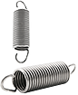
Extension
Springs
For example, when the following conditions are given, the material diameter, number of active coils, spring constant, and stress can be calculated as follows.
Ensure the length when mounted is 160 mm, load when mounted is 176 N, maximum length is 180 mm, maximum load is 275 N, outer diameter is 36 mm or less, both ends of the spring have U hooks with the same length of 20mm or more. Design an extension spring that has a fatigue strength of 1×10⁷ cycles or more at normal temperature. The material is SWP-A. The initial tension is standard. The maximum tensile stress is 0.7 or less and the maximum shear stress shall be 0.45 or less in consideration of fatigue.
Determine material diameters and other spring specifications that satisfy these conditions. The material diameter in this case is φ4.0 mm.
The tensile strength (σB) of SWP-A with a material diameter of φ4.0 mm is 1670 N/mm2.
If the outer diameter of the coil is φ36.0 mm, the spring index will be 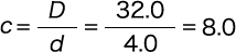
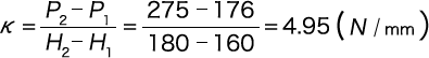
Also, the spring constant from the given conditions is as per the following formula.
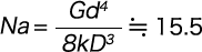
The number of active coils is as per the following formula.
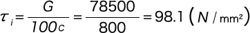
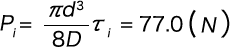
Next, the initial tension is calculated. τi is calculated from formula (1-18).
From the formula (1-17), the initial tension (Pi) is as per the following formula.
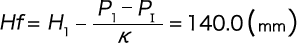
Therefore, the free length (Hf) is as per the following formula.
The hook length on one side is as follows.
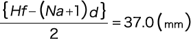
This satisfies the given condition that the hook length is 20 mm or more.
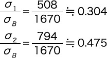
The lower limit stress (σ1) and the upper limit stress (σ2) of the maximum tensile stress generated from the U hook part are calculated according to the formula (1-).
At this time, the numerical formula obtained from the formula (1-16) is 1.134.
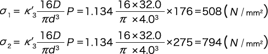
From the stress value, calculate the stress coefficient: 
When these coefficients are plotted in Figure 4, it can be observed that the fatigue strength is 1×10⁷ cycles or more.
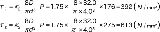
The lower limit stress (τ1) and the upper limit stress (τ2) of the maximum shear stress generated from the U hook part are calculated according to the formula (1-11).
At this time, if the hook rising radius (center) (r2) is 4.0, the 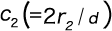 will be 2.0.
Also, K2=1.75 is obtained from the formula (1-12).
Calculate stress coefficient formula from stress value
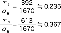
When these coefficients are plotted in Figure 3, it can be observed that it has a fatigue strength of 1 × cycles or more.
 Product information
 Search By Industries