![]()


Spring Design
Design information for engineers, such as spring calculation formulas,
which are the basis of spring design, can be found here.
- Tokai Spring HOME
- Spring Design
- Compression Springs: Calculation Formulas
Compression
Springs
Meaning of Symbols
The symbols used for compression springs design are shown in Table 1 below. The values of the transverse elastic modulus (G) are based on Table 2.
The symbols used in tables and calculation formulas here are in accordance with JIS (Japanese Industrial Standards). The equivalent symbols that are used by ISO are shown in brackets [] next to JIS’ symbols.
Table 1. Symbols and units used in calculations
(Includes the comparison symbols between JIS, ISO)
| Symbols JIS [ISO] |
Meaning of Symbols | Unit |
|---|---|---|
| d | Material diameter | mm |
| D1 [Di] | Coil inner diameter | mm |
| D2 [De] | Coil outer diameter | mm |
| D | Coil mean diameter | mm |
| Nt [nt] | Total number of coils | — |
| Na[n] | Number of active coils | — |
| Hs [Lc] | Solid height | mm |
| Hf [L0] | Free length | mm |
| c=D/d | Spring index | — |
| G | Transverse elastic modulus | N/mm2 |
| P [F] | Load applied to the spring | N |
| δ [s] | Spring deflection | mm |
| k [R] | Spring constant | N/mm |
| τ0 | Torsional stress | N/mm2 |
| τ [τK] | Torsional correction stress | N/mm2 |
| κ | Stress correction factor | — |
| μ | Coefficient of friction | — |
| ν | Seating coefficient | — |
Table 2. Transverse elastic modulus: G(N/mm2)
| Material | G Value | |
|---|---|---|
|
Spring steel material Hard steel wire Piano wire Oil-tempered wire |
7.85×10⁴ | |
| Stainless Steel | SUS304(Correspond to X5CrNi18-9,1.4301,S30400) SUS316(Correspond to X5CrNiMo17-12-2,1.4401,S31600) SUS631J1 |
6.85×10⁴ 6.85×10⁴ 7.35×10⁴ |
| Brass wire | 3.9×10⁴ | |
| Nikel-silver wire | 3.9×10⁴ | |
| Phosphor bronze wire | 4.2×10⁴ | |
| Beryllium copper wire | 4.4×10⁴ | |
Basic Calculation Formulas Used for Compression Springs Design
Relationship between Compression Springs Load and Spring Constant / Deflection
As the load of a spring with linear characteristics is proportional to the deflection, it becomes

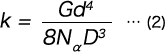
Calculate the Spring Constant from the Dimensions of the Compression Springs
In a compression compression springs, deflection is caused by twisting the wire diameter, and therefore the spring constant (k) is as follows.
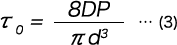
Torsional Stress of Compression Springs
Torsional Correction Stress of Compression Springs

Solid Height of compression springs (When the End Surface is Ground)

Mechanical Properties by Material at High Temperature for Compression Springs
Table 3. Transverse elastic modulus of compression springs by temperature(N/mm2)
| Material | Environment | 100℃ | 200℃ | 300℃ | 400℃ | 500℃ | 600℃ |
|---|---|---|---|---|---|---|---|
| SUP10(Correspond to 51CrV4,6150) | Normal | 76500 | 74300 | — | — | — | — |
| SUS304(Correspond to X5CrNi18-9,1.4301,S30400) | Corrosion resistance / High temperature | 68100 | 66200 | — | — | — | — |
| SUS316(Correspond to X5CrNiMo17-12-2,1.4401,S31600) | Corrosion resistance / High temperature | 68100 | 66200 | — | — | — | — |
| SKD4 | High temperature | 77000 | 74700 | 71600 | 69000 | — | — |
| INCONEL X750 | Corrosion resistance / High temperature | 77700 | 76600 | 74700 | 72800 | 70900 | — |
| INCONEL 718 | Corrosion resistance / High temperature | 74700 | 72400 | 70100 | 67800 | 65900 | 63600 |
| C5191 | Corrosion resistance | — | — | — | — | — | — |
Table 4. Permissible stress of compression Springs by temperature(N/mm2)
| Material | Stress Position | 100℃ | 200℃ | 300℃ | 400℃ | 500℃ | 600℃ |
|---|---|---|---|---|---|---|---|
| SUP10(Correspond to 51CrV4,6150) | τ0 | 490 | 410 | — | — | — | — |
| SUS304(Correspond to X5CrNi18-9,1.4301,S30400) | τ0 | 0.7a | 0.5a | — | — | — | — |
| SUS316(Correspond to X5CrNiMo17-12-2,1.4401,S31600) | τ0 | 0.8a | 0.6a | — | — | — | — |
| SKD4 | τ0 | 550 | 490 | 430 | 350 | — | — |
| INCONEL X750 | τ | 482 | 482 | 482 | 482 | — | — |
| INCONEL 718 | τ | 519 | 519 | 519 | 519 | — | — |
| C5191 | τ0 | — | — | — | — | — | — |
※Click here for more information to design springs from INCONEL which can be used in extreme temperatures of 400℃ or more.
Calculation Formulas for Combined Compression Springs
Series and Parallel Compression Springs
When designing a spring, if possible, one spring should be designed so that the conditions can be met,
but if the design conditions simply cannot be met by one spring, sometimes the design conditions are met by combining multiple springs.
There are two ways to combine springs: a series method that stacks the springs vertically and a parallel method that arranges them horizontally. Such a classification applies not only to compression springs, but also to disc springs and other types of springs, which are similarly used in series or parallel combinations. From the viewpoint of load, the combination method in which the forces acting on each spring are equal is called series, and the combination method in which the displacement of each spring is equal is called parallel.
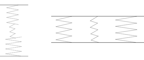
Fig1. Series and Parallel Combinations of Compression Springs
An example of using three compression springs is shown by the fig1. When the spring constant of n springs is Kn (k1, k2, and so on), the total spring constant (K) when these springs are combined in parallel and series is given by the following formula.

Formula 1. Parallel spring constant calculation formula

Formula 2. Series spring constant calculation formula
In parallel combination, the overall spring constant increases as the number of compression springs increases, whereas in series combination, the overall spring constant decreases as the number of compression Springs increases.
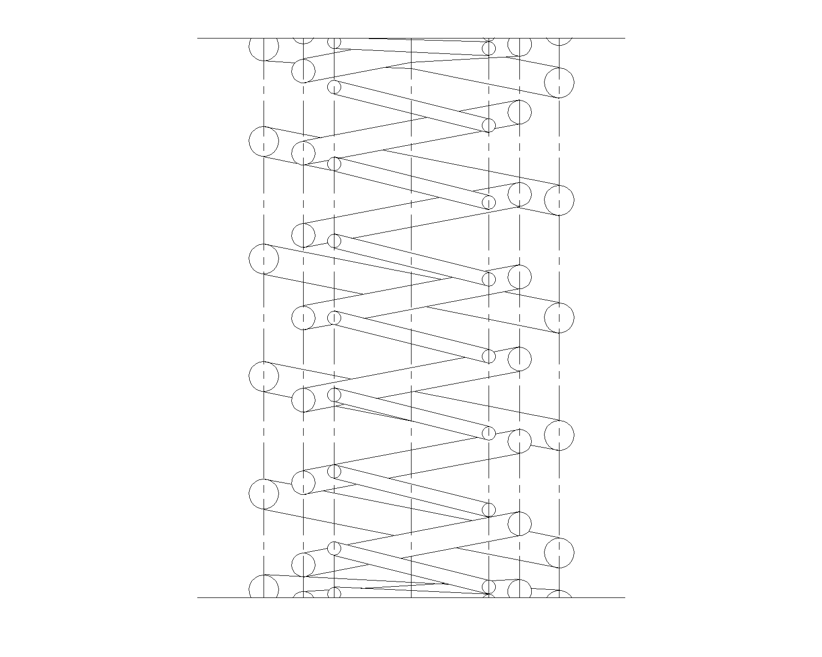
Fig2. Main and Sub Springs
We mentioned that for parallel combination, the springs are arranged side by side, but this will take up space if you simply arrange them this way and so it is common to combine the springs internally and arrange them concentrically as shown in Fig2. This is sometimes called the main and sub springs. The lower, longer spring is called the main, and the upper, shorter spring is called the sub spring.
However, in the case of concentric combinations, it is necessary to alternately change the winding direction or to secure a certain gap between the springs so that the springs do not get entangled.
Also, by devising a combination of springs, it is possible to create nonlinear spring characteristics as shown in the figures a and b below.
For example, in the event the spring characteristics shown in Fig3 are required, it is necessary to combine springs with different free lengths or solid loads in series. The spring characteristics shown in Fig4 can be obtained by inserting a spring into the mechanism shown in Fig5 and making a combination of [upper spring constant] < [lower spring constant].
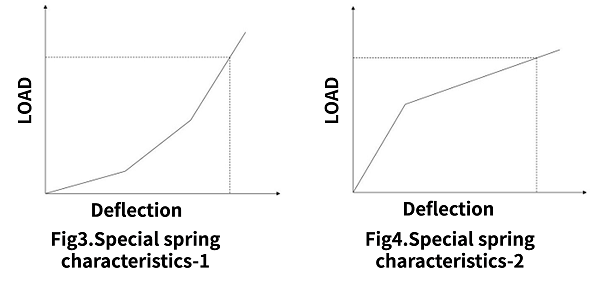
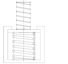
Fig5 Mechanism for Obtaining Special Spring Characteristics
Calculation Formulas of Elastic Potential Energy
Energy stored in the spring
When a load is applied to the spring, its energy gets accumulated in the spring.
Energy (U) accumulated in the spring corresponds to the area surrounded by the load (P) – the displacement (δ) curve in Fig6.
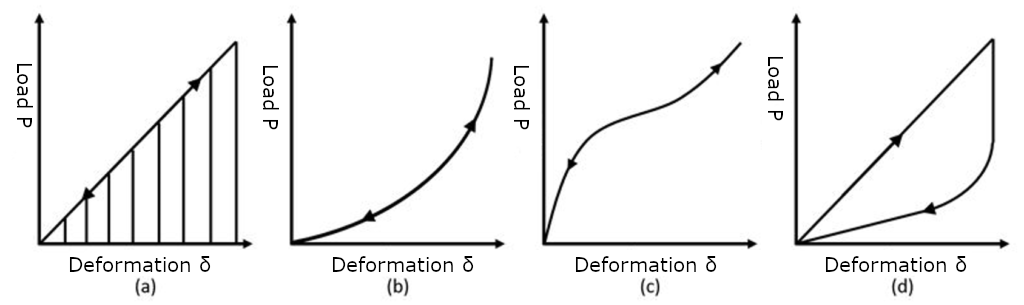
Fig6. Energy Accumulated in the Springs

Formula 3
This is generally known as the spring accumulated energy formula.

Formula 4
Formula 4 is when there is a linear relationship between the two, as shown in (a) above. In other words, it is only in the case of Formula 5 below.

Formula 5
The accumulation and release of energy as shown in (a), (b), and (c) of Fig6 when load is applied and removed, generally passes through the same load-displacement curve (straight line), and so all the energy accumulated by applying a load is released in the process of removing the load. However, in the case of a spring characteristic with a hysteresis loop as shown in Fig6 (d), the energy of the area surrounded by the loop is consumed in one cycle from when the load is applied to when the load is removed.
Calculation Formula for Spring Vibration of Compression Springs
The Compression Spring Has Its Own Frequency
When a spring is subject to a load, deformed, or a force is applied and the force is removed, the spring vibrates. The frequency of this vibration differs depending on the spring, and each has its own unique frequency. When the mass of the spring itself is m, its natural frequency (f) can be represented as follows.

Formula 6
Here, α is a constant that depends on the conditions for fixing the spring and the direction of vibration.
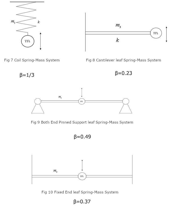
As shown in Fig7, 8, 9, and 10, the natural frequency (f0) when an object of mass (m) is fixed by a spring of mass (ms) and the object is vibrated can be represented as follows.

Formula 7
(Here, we will also explain this in the case of leaf springs.)
As the spring mass (ms) is often smaller than the mass (m) of the object, it is generally considered to be β = 0. However, when the mass of the spring must be considered, it can be approximated as β = 0.49 in Fig9 or β = 0.37 in Fig10.
When designing a spring, it goes without saying that the spring constant is important, but it is often the case that this natural frequency must also be taken into consideration.
Elastic Collision Calculation Formula
Shock Absorption is Where Springs Come in Handy
A spring may be used as an effective means to soften the impact of a collision. As the criteria for evaluating the ability to soften a collision, the buffer efficiency (η) is defined as follows.

Formula 8
Here, M is the mass of the collision side, v0 is the collision speed, Pmax is the maximum collision force, and δmax is the maximum displacement on the collision side. The value of η is between 0 and 1. In an ideal case, it is 1, but in that case, the collision efficiency (η) of a spring with a fixed spring constant is 1/2.
Buckling
Displacement in lateral direction
When a shaft load is applied to an elongated column, a phenomenon occurs in which the column is suddenly displaced laterally.
This is called buckling.
The load when buckling occurs is called the marginal buckling load.
Also, compression springs buckle when compressing to a certain height if large aspect ratio(Ratio of free height to mean coil diameter).
Buckling of the compression spring does not essentially change from buckling of long column.
By equivalently replacing the compression spring with one pillar on the coil center line, it is possible to analyze in exactly the same way as in the long column.
However, in the case of compression springs, it is necessary to take into account the effects of shear deformation and the change in length of the spring which could be ignored with the long pillar.
In the formula, E is the Young’s modulus, G is the transverse elastic modulus, and D is the mean coil diameter.
As shown in (a) of the fig11, μ is 1 when the both ends of the spring are rotatably supported, and 4 when the both ends are fixedly supported as shown in (b).
In addition, ξ becomes 1 if the section is circular in cross section.
The equation does not include the influence of wire diameter and number of coils, but because it is analyzing it by replacing the spring with a pillar.
According to a strict analysis that takes into consideration the helical structure of the spring, these effects are small with the springs usually used, so this equation is considered practical in practice.
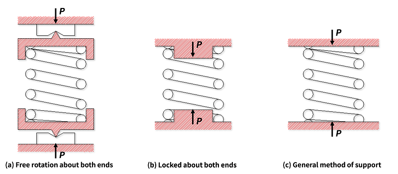
Fig11. The state of supporting for compression springs
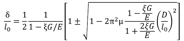
Formula 9. Ratio of deflection and free height until buckling of compression spring
 Product information
 Search By Industries
- Aerospace
- Machine tools
- Oil / Gas / Energy
- Architecture / Seismic isolation
- Engineering Science / Academic Research
- Telecommunication / Electronic equipment
- Environmental Chemical Industries
- Steel Mill Equipment
- Machinery / equipment
- Robots
- Medical / Healthcare
- Transport equipment
- Agricultural machinery
- Food machinery
- Mining / Heavy equipment
- Ships / Marine Industries
- Sluices / Bridges
- Professional
- Leisure equipment
- Special springs
- Spring Testing, Inspection, and Analysis Services
- RE:SPRING Service