![]()


Spring Design
Design information for engineers, such as spring calculation formulas,
which are the basis of spring design, can be found here.
- Tokai Spring HOME
- Spring Design
- Flat Springs: Calculation Formulas
Flat
Springs
Selecting the shape to get the required spring load or deflection with a limited volume and estimating the position and magnitude of the maximum stress generated in the spring are important when designing a leaf spring. The formulas shown in general materials can be used for relatively simple spring shapes, but since there are various shapes and applications of leaf springs in reality, we will introduce calculation formulas for flat springs by shapes and applications here.
– Table of Contents –
- Calculation Formulas for Flat Springs by Shapes
- Cantilever Springs with Rectangular Cross-section
- Calculation Formulas for Flat Springs with Trapezoidal Cantilever
- Calculation Formulas for Flat Springs with Joggled Plate Width
- Calculation Formulas for Flat Springs with Circular Cantilever
- Calculation Formulas for Flat Springs with Arc-Shaped Cantilever
- Calculation Formula for Ring-shaped Flat Springs
- Calculation Formulas for Flat Springs with Half-circle and Quarter-circle Combination
- Calculation Formulas for Flat Springs with Arc Constrained in the Horizontal Direction
- Calculation Formulas for Flat Springs with Arc and Straight Line Part
- Calculation Formula for Flat Spring with Arc and Straight Line Part (No.1)
- Calculation Formula for Flat Spring with Arc and Straight Line Part (No.2)
- Calculation Formula for Flat Spring with Arc and Straight Line Part (No.3)
- Calculation Formula for Flat Spring with Arc and Straight Line Part (No.4)
- Calculation Formula for Flat Spring with Arc and Straight Line Part (No.5)
- Calculation Formulas for Flat Springs with Complicated Combination of Arc and Straight Line Part
- Flat Spring Calculation Formulas by Characteristics and Applications
1 Calculation Formulas for Flat Springs by Shapes
・1-1 Cantilever Springs with Rectangular Cross-section
The simplest flat spring is a cantilever spring with a rectangular cross-section.
When the fixed end is A and the free end is B, and the load P is applied to point B, the calculation formula is as follows.

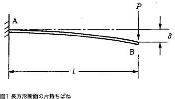
Here, I is the second moment of area.
It is expressed by
![]() , and when
, and when ![]() is large, it is
is large, it is ![]()
Thus, the calculation formula for when ![]() is large is
is large is 
ν represents the Poisson’s ratio, and in the case of steel, ν ≈ 0.3. The maximum stress is at the fixed end and is represented by the formula below.

Table 2 shows the longitudinal elasticity modulus (E) value of the main flat spring materials.
Table 1. Symbols and units used in calculations
| Symbol | Meaning of Symbol | Unit |
|---|---|---|
| h | Plate Thickness | mm |
| b | Plate Width | mm |
| l | Distance From The Fulcrum To The Load Point | mm |
| r | Arc Radius | mm |
| E | Longitudinal Elastic Modulus | N/mm2 |
| I | Second Moment of Area | mm4 |
| Z | Section Modulus | mm3 |
| P | Load (force) Applied To The Spring | N |
| δ | Deflection At Load Point | mm |
| k | Spring Constant | N/mm |
| σ | Bending Stress | N/mm2 |
| ν | Poisson’s ratio | – |
Table 2.Longitudinal elastic modulus:E(N/m㎡)
| Material | E Value | |
|---|---|---|
| Spring Steel Material | 206×103 | |
| Stainless Steel | SUS301 SUS304(Correspond to X5CrNi18-9,1.4301,S30400) SUS631(Correspond to X7CrNiAl17-7,1.4568,S17700) |
186×103 186×103 196×103 |
| Phosphor Bronze Wire | 98×103 | |
| Beryllium Copper Wire | 127×103 | |
・1-2 Calculation Formulas for Flat Springs with Trapezoidal Cantilever

Figure 2
As shown in Figure 2, when the plate thickness of the flat spring is fixed and the plate width changes linearly, the deflection of the free end![]() is as per the following formula.
is as per the following formula.

Formula 4
To calculate B in the formula, use the following two formulas according to the plate thickness.
If the plate is thick, use the formula below.

If the plate is thin, use the following formula:

Also, the value ![]() in the formula can be calculated from Figure 3 by β = b1 / b.
in the formula can be calculated from Figure 3 by β = b1 / b.

Figure 3
・1-3 Calculation Formulas for Flat Springs with Joggled Plate Width

Figure 4
As shown in Figure 4, the deflection ![]() at the free end of a flat spring with a fixed plate thickness and a joggled plate width is as per the following formula.
at the free end of a flat spring with a fixed plate thickness and a joggled plate width is as per the following formula.

Formula 5
Here,![]() 、
、![]() are the deflection and deflection angle of the joggled part A due to P, and
are the deflection and deflection angle of the joggled part A due to P, and ![]() is the deflection at the free end of the cantilever with length
is the deflection at the free end of the cantilever with length ![]() l2 and plate width
l2 and plate width ![]() .
.
・1-4 Calculation Formulas for Flat Springs with Circular Cantilever

Figure 5
When the vertical load (P) acts on the free end with the shape as shown in Figure 5 in which the center of the plate thickness is a straight line and the center line of the plate width is an arc, the deflection (δφ) at any position φ is as per the following formula.

Formula 6
Here, C represents the torsional strength of the plate.
・1-5 Calculation Formulas for Flat Springs with Arc-Shaped Cantilever

Figure 6
Generally, Castigliano’s theorem is used to calculate the deflection when a load is applied to a cantilever spring whose center line of plate thickness is an arc. The calculation results using this theorem are shown below.
When the vertical load (P) and the horizontal load (W) are simply applied to the position of the central angle ![]() on the arc-shaped flat spring shown in Figure 6, deflection
on the arc-shaped flat spring shown in Figure 6, deflection ![]() in the y-direction and deflection
in the y-direction and deflection ![]() in the x-direction at the central angle
in the x-direction at the central angle ![]() position are as follows.
position are as follows.
Deflection ![]() due to P
due to P![]()
When ![]() :
:

Formula 7
When ![]() :
:

Formula 8
Deflection ![]() due to W:
due to W:
When ![]() :
:

Formula 9
When ![]() :
:

Formula 10

Figure 7
In Figure 7, δy and δx ![]() 、
、![]() are as follows.
are as follows.

Formula 11

Formula 12

Figure 8
In Figure 8, δy and δx are as follows.

Formula 13

Formula 14
The maximum stress ![]() due to P always occurs at the fixed end.
due to P always occurs at the fixed end.

Formula 15
The maximum stress due to W occurs at point A in Figure 8 for ![]() and at the fixed end for
and at the fixed end for ![]() .
.

Formula 16
・1-6 Calculation Formula for Ring-shaped Flat Springs

Figure 9
The circular spring shown in Figure 9 is vertically symmetrical, and so the total deflection is twice the deflection of the shape in Figure 8.

Formula 17
・1-7 Calculation Formulas for Flat Springs with Half-circle and Quarter-circle Combination

Figure 10
In the flat spring with the combination of the half-circle and the quarter-circle shown in Figure 10, the deflection is as per the following formula.

Formula 18
The maximum stress occurs at the fixed end can be calculate with the following formula:

Formula 19
・1-8 Calculation Formulas for Arced Flat Springs

Figure 11
The deflection of the free end of the shape shown on the left side of Figure 11 is as per the following formula.

Formula 20
In the case of an arc that is constrained in the horizontal direction as shown on the right side of Figure 11, the deflection can be calculated with the following formula.

Formula 21
In both cases, the maximum stress is calculated with the following formula.

Formula 22
・1-9 Calculation Formulas for Flat Springs with Arc and Straight Line Part
・1-9-1 Calculation Formula for Flat Spring with Arc and Straight Line Part (No.1)

Figure 12
As shown in Figure 12, when the straight-line part (AB) and the circular arc part (BD) are combined, one end (D) is fixed, and the vertical load (P) or the horizontal load (W) acts on the other end (A), ![]() and
and ![]() will be as follows.
will be as follows.

Formula 23

Formula 24
When ![]() ,
,

Formula C25
If W acts, the formula will be as below.

Formula 26

Formula 27
Here, ![]() in the formula represents
in the formula represents ![]()
The maximum stress occurs at the fixed end when ![]() , and at the point C when
, and at the point C when ![]() .
.
・1-9-2 Calculation Formulas for Flat Springs with Arc and Straight Line Part (No.2)

Figure 13
The spring in Figure 13 is a combination of the two springs in Figure 12, and the deflection ![]() is
is ![]() times the deflection obtained in formula 23.
times the deflection obtained in formula 23.

Formula 28

Figure 14
As shown in Figure 14, the deflection of the A end of the spring with a straight line part and an arced part is as per the following formula.

Formula 29
Here, ![]() and
and ![]() .
.
The maximum bending stress occurs at point C can be calcumated with the following formula.

Formula 30
In the case of ![]() , if
, if ![]() , the maximum stress occurs at the fixed end, and when
, the maximum stress occurs at the fixed end, and when ![]() and
and ![]() , the formula is as follows.
, the formula is as follows.

Formula 31
・1-9-3 Calculation Formulas for Flat Springs with Arc and Straight Line Part (No.3)

Figure 15
In the case of the shape shown in Figure 15, it is possible to calculate the deflection of part A by dividing the AC part and the CD part, doubling the deflection of formula 25 and calculating the deflection of each formula before combining them.

Formula 32
・1-9-4 Calculation Formulas for Flat Springs with Arc and Straight Line Part (No.4)

Figure 16
As shown in Figure 16, the straight part is fixed, and so when a load is applied to the A end of the arc part, the vertical deflection ![]() and the horizontal deflection
and the horizontal deflection ![]() of the A end are as per the following formula when the P load acts as
of the A end are as per the following formula when the P load acts as ![]() .
.

Formula 33

Formula 34
When the W load acts, the formula is as follows.

Formula 35

Formula 36

Figure 17
For the shape in Figure 17, when the load (P) acts, the formula is as follows.

Formula 37

Formula 38
When W acts, the formula is as follows.

Formula 39

Formula 40
It is represented here as ![]() .
.
・1-9-5 Calculation Formulas for Flat Springs with Arc and Straight Line Part (No.5)

Figure 18
For a spring with the shape shown in Figure 18 that combines an arc with a small curvature radius and a straight line, the deflection that excludes the radius of the arc is expressed by the following formula.

Formula 41
The maximum stress occurs at the BC part when ![]() , can be calculated with the following formula.
, can be calculated with the following formula.

Formula 42
If ![]() , the maximum stress occurs at the fixed end, with the formula as follows.
, the maximum stress occurs at the fixed end, with the formula as follows.

Formula 43
・1-9-6 Calculation Formulas for Flat Springs with Complicated Combination of Arc and Straight Line Part
The shape of the flat spring is often a complex combination of an arced part and a straight part. The formulas introduced so far can be used for the shape of the thin leaf springs. The shapes and calculation formulas shown below can be used as practical concepts.

Figure 19
The shape in Figure 19 is considered to be a combination of the two shapes in Figure 13, and the deflection can be calculated by doubling that of Formula 28.

Figure 20
In the shape of Figure 20, both ends are similar to Figure 10, and the stress formula can be shown with Formula 19. The deflection on one side with respect to the axis of symmetry is an added part from Formula 18, and the deflection on one side is given by the formula below.

Formula 44
The deflection formula is:

Formula 45
2.Flat Spring Calculation Formulas by Characteristics and Applications
・2-1 Calculation Formulas for Flat Springs with Nonlinear Characteristics

Fifure 21
A flat spring with non-linear characteristics, as shown in Figure 21, is achieved by adopting an adhesive part structure where the fixed adhesive position changes in sequence due to deflection.
The formula for a flat spring with non-linear characteristics is as follows.
Formula 46
・2-2 Calculation Formulas for Flat Springs Which are Subject to Axial and Lateral Loads

Figure 22
Flat springs are found in applications such as load measuring equipment as the one shown in Figure 22. One end is fixed and the other end can move laterally but cannot rotate. In this case, assuming that the axial load (P) is smaller than the buckling load, the deflection ![]() and stress
and stress ![]() due to the lateral load (Q) are expressed by the following formulas.
due to the lateral load (Q) are expressed by the following formulas.

Formula 47

Formula 48
If P is larger than the buckling load, the formula above is multiplied by the coefficients ![]() and
and ![]() determined by
determined by ![]() . Here,
. Here, ![]() is Euler’s buckling load and
is Euler’s buckling load and ![]() . Here, the coefficients
. Here, the coefficients ![]() and
and ![]() are as per the following formulas.
are as per the following formulas.

Formula 49

Formula 50
・2-3 Calculation Formulas for Flat Springs with Large Deflection
・2-3-1 Flat Springs with a Rectangular Cross-section

Figure 23
When the deflection is large, ![]() changes to
changes to ![]() . Figure 24 shows the calculation result with this effect added.
. Figure 24 shows the calculation result with this effect added.

Figure 24
The horizontal axis of the figure shows ![]() , and the vertical axis shows
, and the vertical axis shows ![]() ,
, ![]() .
. ![]() represents the bending stiffness of the plate, and when
represents the bending stiffness of the plate, and when ![]() is large,
is large, ![]() . As is clear from Figure 24, when the value of
. As is clear from Figure 24, when the value of ![]() is small, that is, when the load P is small,
is small, that is, when the load P is small, ![]() and
and ![]() are close to 1, and when
are close to 1, and when ![]() ,
, ![]() and
and ![]() . Therefore, in the case of this degree of deformation, it is deemed unnecessary to handle it as a large deflection in terms of the spring’s practical application.
. Therefore, in the case of this degree of deformation, it is deemed unnecessary to handle it as a large deflection in terms of the spring’s practical application.
・2-3-2 Flat Springs with Trapezoidal Cantilever

Figure 25

Figure 26
Figures 25 and 26 show the approximate results when the deflection of the flat spring with a trapezoidal cantilever is large. The horizontal axis is ![]() and the vertical axis shows the rate of decrease in deflection or stress with
and the vertical axis shows the rate of decrease in deflection or stress with ![]() as a parameter. This just needs to be applied to the formula
as a parameter. This just needs to be applied to the formula ![]() .
.
 Product information
 Search By Industries
- Oil / Gas / Energy
- Engineering Science / Academic Research
- Telecommunication / Electronic equipment
- Environmental Chemical Industries
- Machinery / equipment
- Robots
- Transport equipment
- Mining / Heavy equipment
- Professional
- Culture / Art
- Special springs
- Spring Testing, Inspection, and Analysis Services
- RE:SPRING Service