![]()


Spring Design
Design information for engineers, such as spring calculation formulas,
which are the basis of spring design, can be found here.
- Tokai Spring HOME
- Spring Design
- Compression Springs: Things To Note In Spring Design
Compression
Springs
About Design Calculation
Notes About the Design
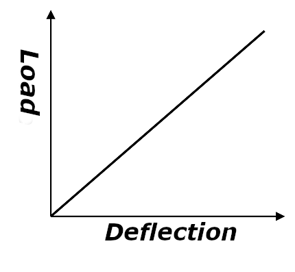
(1) Characteristics of Compression Springs
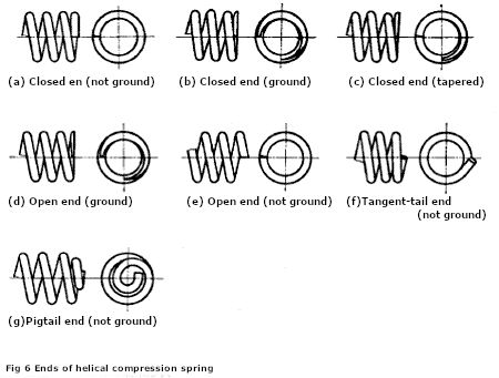
(2) End Shape
Fig 2. (a) to (g) shows the end shape of the compression spring. The closed end is often used for general use. To improve the washer of the spring, a material whose end surface is ground or tapered is used. Tapered materials are often used in mass-produced products, and tangent tails and pigtails are often used for automobile suspension springs.
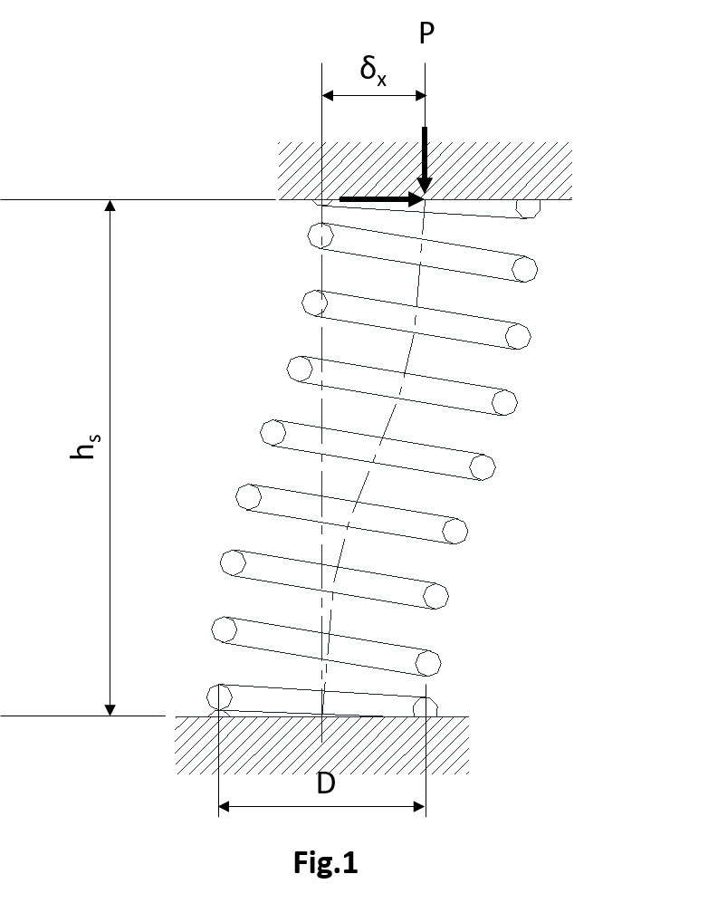
(3) Lateral Stiffness of Compression Springs
One of the properties of a compression spring is its ability to act as a spring not only along coil center line.
Spring constant in vertical direction and horizontal direction
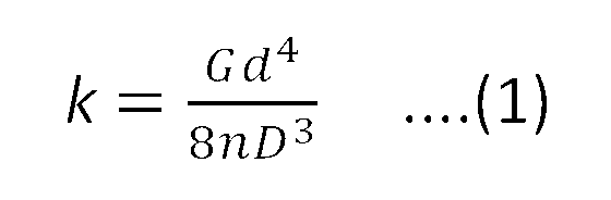
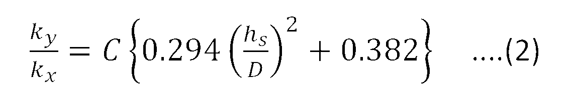
If the coil center line is oriented vertically, and the direction perpendicular to it is horizontal, the spring constant in vertical direction is defined by the expression (1). In this case, the spring constant in horizontal direction is called lateral stiffness, and can be obtained using the expression (2).
Spring constant in vertical direction
Spring constant in horizontal direction
ky=expression (1)=P/δs
kx:lateral stiffness
hs:spring height at vertical load P=h0-δs
C : a coefficient determined by aspect ration and (vertical deflection / free height)
As seen from the expression (1), if the spring shape is known, the ky value can be determined unambiguously. On the other hand, it is necessary to remember that the lateral stiffness depends on vertical deflection of the spring.
In any case, if kx and ky are required, they may be calculated by dividing the spring deflection caused by an oblique load in arbitrary direction into vertical and horizontal components.
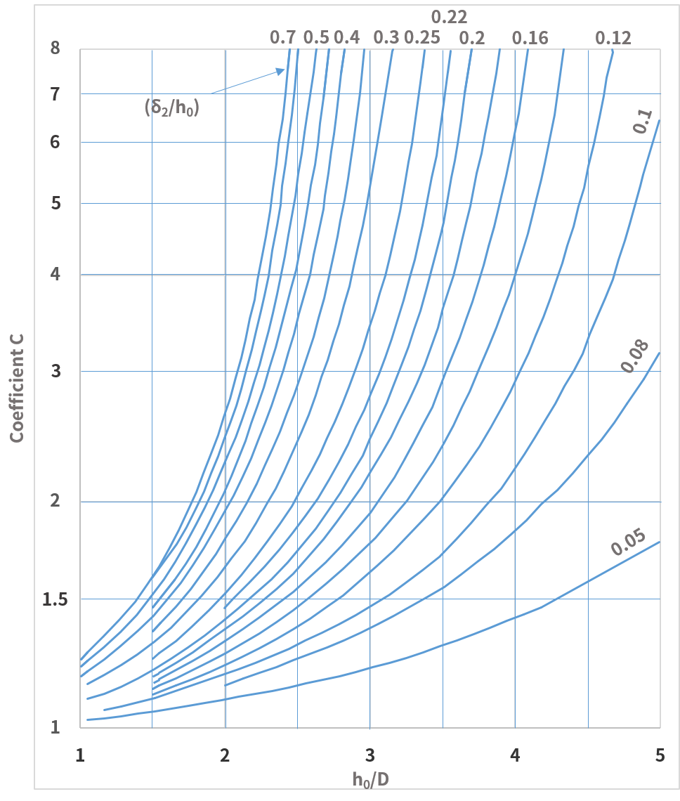
Fig.4
Can compression spring also act on moments?
Compression spring can also act on moments.
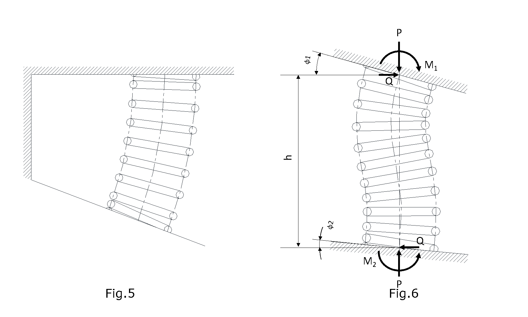
This property is used in suspension springs of passenger cars, where springs are incorporated in link mechanisms as shown on the fig.5. Here a moment is applied to the spring besides vertical and horizontal loads. Fig.6 shows the state where a compression spring is compressed to the height h by support plates tilted by angles φ1 and φ2.
The vertical P and horizontal Q components of reaction force of supports can be obtained using expressions (3) , (4) and the q is (5).
And the moment is M1(6) and M2(7)
P=expression (3)
Q=expression (4)
q=expression (5)
The moment M1= expression (6)
The moment M2= expression (7)

(4) About Surging in Compression Springs
When a sinusoidal forced oscillation is applied to a spring, the surge waveforms a stationary wave.
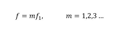
When the relationship between the frequency f of the external force and the natural frequency f1
of the spring satisfies the equation (a), a resonance phenomenon called surging occurs.
Here the first natural frequency f1 is determined by the following equation.

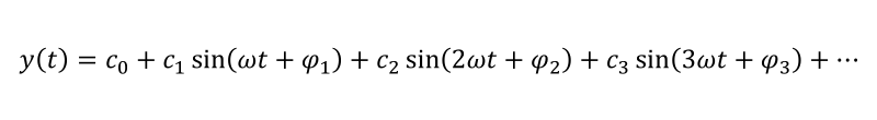
When the rotational speed ω of camshaft is constant like in valve springs of modern engines, the valve lift curve y(t) is represented by the Fourier series as shown below.
When the spring is in the primary resonance state with nth-order wave cosign (nωt + φn), the maximum fluctuating stress τs generated in the spring is the same stress τs (t) that occurs when the spring is statically compressed to y(t) only. This stress is given by the following equation.


Fig.7. Stress variation due to surging
Fig.7 shows the stress diagram of a valve spring when the surging occurs. τ1 on the figure is the stress caused by initial compression applied to the spring at the closed vale position. The minimum τmin and the maximum τ2 stress values at this time can be calculated by equations (e) and (f) correspondently.
(e)(f)
The stress variation range τr is given by the equation (g).
(g)
An example of the resonance curve obtained by oscillation test of valve spring is shown on Fig.8. This curve represents the vibration amplitude of the central coil of the valve spring plotted against the camshaft rotation speed. Peaks on the figure represent the resonance vibrations occurring when the natural frequency of the valve spring matches upper harmonics of the valve lift curve. The heights of the peaks are not constant because the amplitudes cn of the harmonics are not constant.
For example, since the peak #10 corresponding to the 10th upper harmonic occurs at the camshaft rotation speed of 1200, the natural frequency of the valve spring subjected to the test is 10×(1200/60)=200cps=12000cpm.
To prevent the surging, the following methods can be considered.
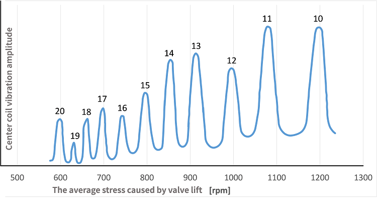
Fig. 8. Valve spring resonance curve example
It is generally difficult to prevent the spring resonance at all harmonics of the valve lift curve within the engine speed variation range.
However, as can be surmised from the fig.8, since the amplitude of upper harmonics decreases as the order of the harmonic increases, the resonance oscillation also decreases inevitably. Therefore, if the spring natural frequency is made as high as possible so that the resonance occurs only at higher order harmonics, this can considerably reduce the effect of surging. However, care should be taken because high natural frequency tends to increase the stress due to initial compression.
Change the shape of cams
For example, if the lowest natural frequency of the valve spring for engine with rotation speed in the range of 2000-3000 rpm is set to 500cps, it will resonate at 10th-15th harmonics. Therefore, it is enough to design the cams so that the amplitude of these harmonics is small.
Use springs with nonlinear characteristics
Since the natural frequency of nonlinear compression coil springs depends on the deflection, it can prevent the resonance phenomenon on upper harmonics.
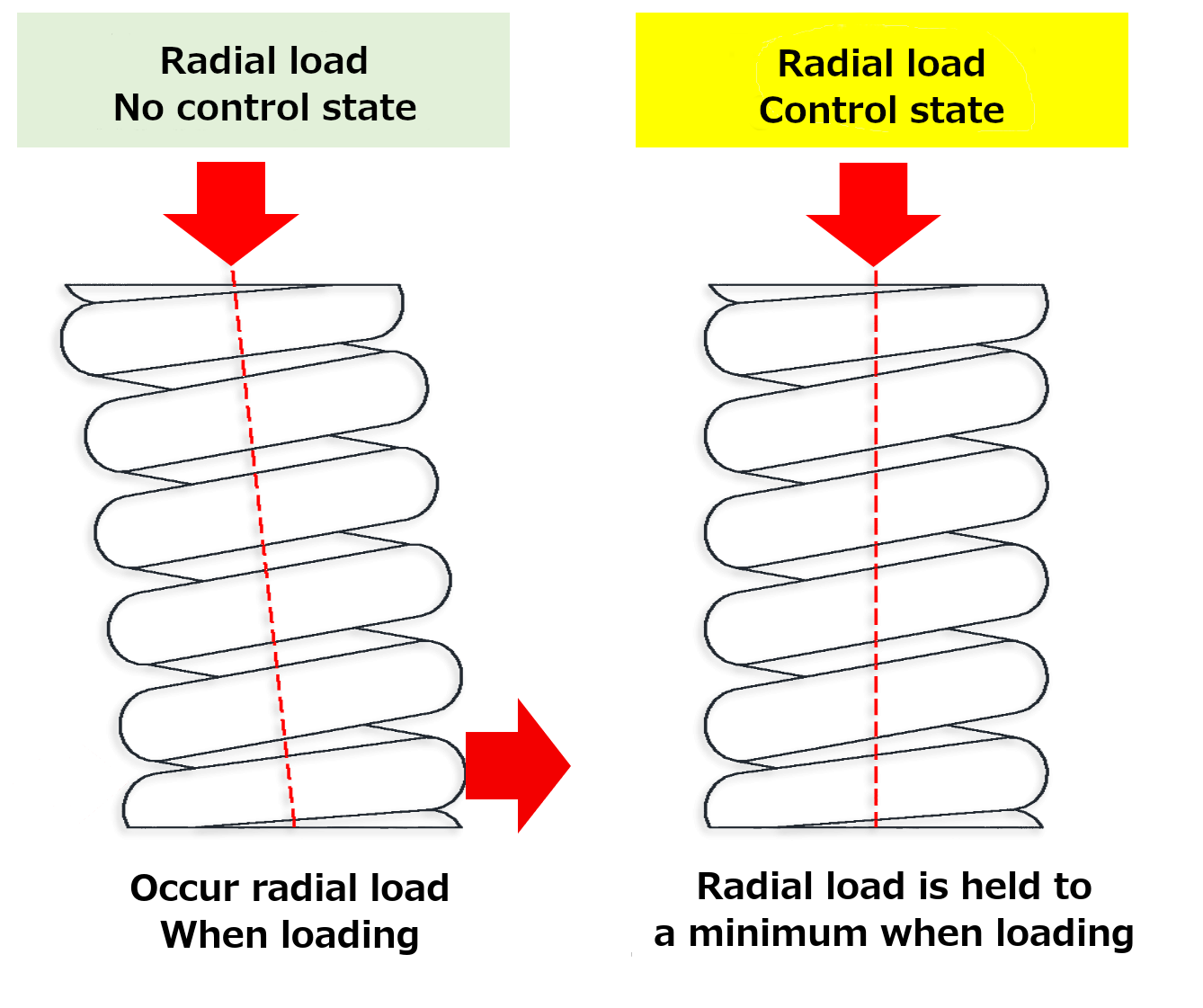
(5) Radial load (lateral load)
(6) Other Considerations
a. Spring index
When the spring index becomes small, the local stress becomes excessive, and when the spring index becomes large or small, the workability of the spring becomes a problem. Therefore, for the spring index, it is preferable to select within the range of 4 to 15 for hot-formed springs and 4 to 22 for cold-formed springs.
b. Aspect ratio
The aspect ratio (ratio of free height and average coil diameter:
 )is set to 0.8 or more to secure a number of active coils, and in consideration of buckling, it is generally preferable to select within the range of 0.8 to 4.
c. Number of active coils
If the number of active coils is less than 3, the spring characteristics will be unstable, and so it is preferable to set the number of active coils to 3 or more.
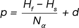
d. Pitch
If the pitch exceeds 0.5 D, the coil diameter generally changes with an increase in deflection (load). Therefore, it is necessary to correct the deflection and torsional stress obtained from the basic formula, and so 0.5 D or less is deemed to be an appropriate pitch.
The pitch is generally estimated according to the following approximate formula.
 Product information
 Search By Industries
- Aerospace
- Machine tools
- Oil / Gas / Energy
- Architecture / Seismic isolation
- Engineering Science / Academic Research
- Telecommunication / Electronic equipment
- Environmental Chemical Industries
- Steel Mill Equipment
- Machinery / equipment
- Robots
- Medical / Healthcare
- Transport equipment
- Agricultural machinery
- Food machinery
- Mining / Heavy equipment
- Ships / Marine Industries
- Sluices / Bridges
- Professional
- Leisure equipment
- Special springs
- Spring Testing, Inspection, and Analysis Services
- RE:SPRING Service