![]()


Spring Design
Design information for engineers, such as spring calculation formulas,
which are the basis of spring design, can be found here.
- Tokai Spring HOME
- Spring Design
- Disc Springs: Calculation Examples
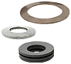
Disc
Springs
Shown here are the calculation examples of load and stress when the disc springs shown in Table 2 are set at 199.8 mm and are compressed by 5.5 mm.
Coefficients Used for Calculation
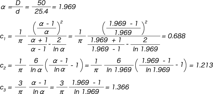
Table 2. Disc Spring Specifications
| Symbol | Unit | Value |
|---|---|---|
| D | mm | 50 |
| d | mm | 25.4 |
| t | mm | 3 |
| H0 | mm | 4.1 |
| h0 | mm | 1.1 |
| E | N/mm2 | 2.06 × 10⁵ |
| n | piece | 2 |
| m | layer | 30 |
| R | mm | 0.3 |
Calculation of Load
The free height (L0) when the disc springs are stacked is as follows.

The defections when mounted and at its maximum (δmin and δmax) are as follows.
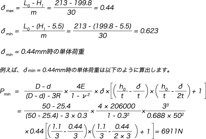
As there are two springs stacked in parallel, the combined load is 6,911 × 2 = 13,822 N.
Similarly, when δ max. = 0.623 mm, the single load is P max. = 9,576 N, and the combined load is 9,576 × 2 = 19,152 N.
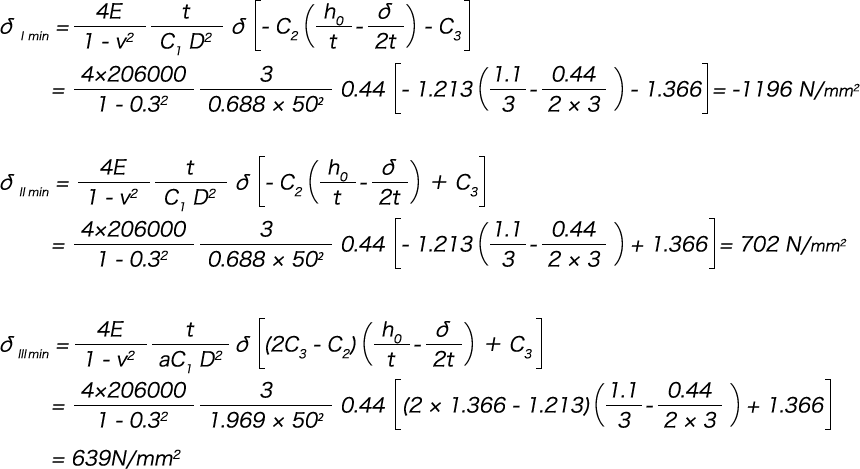
Calculation of Stress
When δ min. = 0.44 mm, the stress of each part is as per the following formula.
Similarly, the stress of each part when δ max. = 0.623 mm is as follows:
σI max =-1658 N/mm2
σII max =1030 N/mm2
σIII max =882 N/mm2
From the results above, the load characteristics of these disc springs are shown in Table 3.
Table 3.
| Load(N) | Height(mm) | Deflection(mm) | Stress(N/mm)2 | ||
|---|---|---|---|---|---|
| σI | σII | σIII | |||
| 0 | 213.0 | 0 | – | – | – |
| 13822 | 199.8 | 13.2 | -1196 | 702 | 639 |
| 19152 | 194.3 | 18.7 | -1658 | 1030 | 882 |
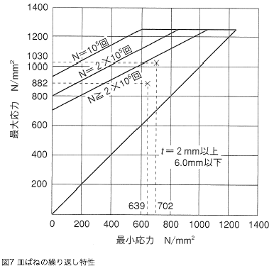
Service Life Estimation
Next, the service life is estimated. The following figure shows the plotting and applying of stresses at angles II and III in Table 3 corresponding to the tensile load. As the line immediately above the plotted points is a line of 2 million cycles, the service life estimation of this spring is 2 million cycles.
 Product information
 Search By Industries
- Aerospace
- Machine tools
- Oil / Gas / Energy
- Architecture / Seismic isolation
- Engineering Science / Academic Research
- Telecommunication / Electronic equipment
- Environmental Chemical Industries
- Steel Mill Equipment
- Machinery / equipment
- Robots
- Transport equipment
- Food machinery
- Sluices / Bridges
- Special springs
- Spring Testing, Inspection, and Analysis Services
- RE:SPRING Service