![]()


Spring Design
Design information for engineers, such as spring calculation formulas,
which are the basis of spring design, can be found here.
- Tokai Spring HOME
- Spring Design
- Compression Springs: How To Calculate Spring Stress
Compression
Springs
1.When Used under a Static Load
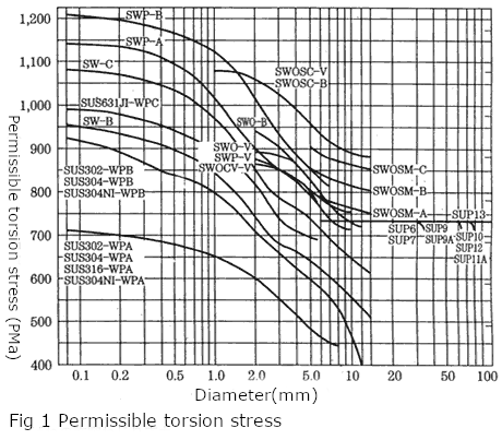
For compression springs that are subject to static loads, JIS B 2704 defines the permissible torsional stress criteria as shown in Figure 1. It is recommended that the normal stress be 80% or less. The stress correction factor need not be considered for this stress.
2.When Used under a Dynamic Load
For SAE, the permissible stresses of the cold-formed compression spring and the hot-formed compression spring are shown in Figure 3 and Figure 4.
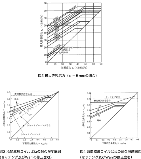
In order to estimate fatigue strength more accurately, it is necessary to carry out a fatigue endurance test.
In addition, the “fatigue strength diagram of torsional stress” can be found in JIS B 2704. However, it does not disclose the durability limit diagram of steels such as stainless steel and heat-resistant steel.
3.Terms Related to Mechanical Properties of Compression Springs
Terms related to mechanical properties of compression springs
3-1 Tensile Strength
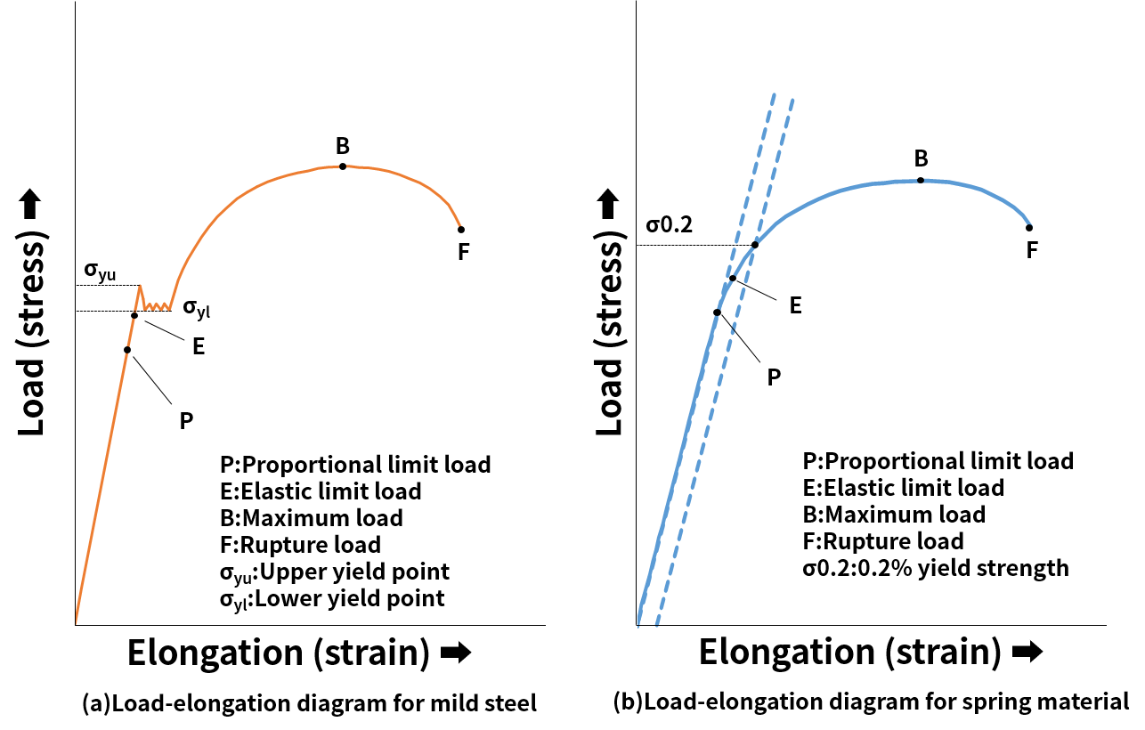
Tensile strength is a value obtained by dividing the maximum load between the start of tensile test and breakage by the cross-section area of the specimen. The tensile test is performed by applying continuously increasing tensile load F to the tensile test specimen with initial cross-section area A0 and initial gauge length L0. The current length L or elongation L-L0 is measured together with the load. A load (force)-elongation diagram shown on the fig. 1, or, using expressions (1) and (2), a stress-strain curve can be obtained from these continuous data. Nominal stress σ=W/A0 (1) Nominal strain ε=(L-L0)/L0 (2)
3-2 Spring Material
The relationship between load and elongation for the test specimen is proportional until a certain load is applied, but after the yield point or yield strength is exceeded, the specimen undergoes plastic deformation, and the stress required to further deform it increases. The stress eventually reaches the maximum nominal stress value (point B). This maximum value σB is called tensile strength. The material between gauge points of the specimen deforms almost uniformly until the point B, that is, the maximum load is reached. However, when the maximum load point is passed, the deformation concentrates in one part of the specimen, causing necking in its outward appearance, and eventually leading to rupture at point F. At this time, the tensile strength can be obtained using expression (3) Tensile strength(N/mm2)=Maximum load during test(N) / Initial cross—section area(mm2) (3)
3-3 Elongation
In the tensile strength, the elongation is the difference between the gauge length L at the time of specimen rupture and the gauge length before test L0. Generally, this difference is expressed as percentage of the initial gauge length L0. (δ)Elongation=Gauge length after test L – Initial gauge length L0 /Initial gauge lengthL0 ×100 (%) (4)
3-4 Area Reduction
In the tensile test, the ratio of the most reduced cross-section area in the vicinity of rupture part to the initial cross-section area Area reduction(φ)=Initial cross-section area(A0)-Reduced cross-section area(A) / Initial cross-section area(A0)×100(%) (5)
3-5 Yield Point
If a material exhibits a clear yielding phenomenon as shown on the fig. 1, the yield stress is used as the yield point. When the upper and lower yield points are clear as in mild steel, the upper yield point σyu is often regarded as the yield point. However, since rigidity, tensile speed and other characteristic of the testing apparatus may cause small errors when determining the value of σyu, the stable value of the lower yield point σy1 also can be adopted as the yield point.
3-6 Yield Strength
If a material does not exhibit a clear yield point as shown on the fig. 1, the nominal stress σ 0.2 that produces a constant permanent strain (usually 0.2% permanent strain) is determined by the offset method and regarded as the yield stress. This yield stress is called the yield strength.
3-7 Proportional Limit and Elastic Limit
If the linear relationship between stress and strain or the applicability range of Hooke’s law is limited by the point P shown on the fig. 1, the nominal stress σP at the point P is called the proportional limit. However, it is very difficult to measure this limit. The stress σE in the point E, where material experiences a slight permanent deformation (0.02% or 0.05%), is called the elastic limit. Since both proportional limit and elastic limit values significantly depend on accuracy of measurement, in practice the yield point or yield stress are often used as evaluation targets.
3-8 Hardness
Hardness can be considered as a measure of degree of material’s resistance to deformation. Since there many different physical definition of hardness, it is often considered not as inherent physical property of the material, but as industrial value obtained by correspondent measurement methods. Hardness measurement methods include methods for measurement of indentation hardness (Vickers hardness, Rockwell hardness, Brinell hardness, etc.), dynamic hardness (Shore hardness, etc.), scratch hardness (Mohs hardness) and other hardness measurement methods.
3-9 Modulus of Longitudinal Elasticity (Young’s Modulus)
In the region below point P in fig. 1a and 1b, a proportional relationship exists between stress σ and strain ε (Hooke’s law). The proportional coefficient of this relationship is called the modulus of longitudinal elasticity E (Young’s modulus). There are also modulus of transverse elasticity G (shear modulus, rigidity), modulus of volume elasticity K and Poisson’s ratio ν.
3-10 Modulus of Transverse Elasticity (Modulus of Elasticity)
The modulus of longitudinal elasticity is the modulus of elasticity in regard to stress caused by tension, compression, bending, etc. However, when a force is applied in the direction of twisting of an object, there are various forces causing angular deformation of the object without changing its length. These forces are called the shear stress. These forces cause shear stress τ and shear strain γ. Below the proportional limit in the shear direction, there is a proportional relationship between the shear stress and the shear strain. The proportional coefficient of this relationship is referred to as the modulus of transverse elasticity and is denoted as G. For an isotropic elastic object the modulus of transverse elasticity can be calculated by expression (6), if its modulus of longitudinal elasticity and Poisson’s ratio are known. G=E/2 (1+ν) (6) Since Poisson’s ratio is almost always 0.3 for many isotropic metals, the expression (6) becomes E = 2.6 G. Because the stress in the compression spring is the shear stress, the modulus of transverse elasticity is used in the spring design.
3-11 Poisson’s Ratio
When stretching a round bar, its length extends within the elastic range and its diameter decreases. The elongation and the diameter reduction are determined by the substance, and their ratio is called the Poisson’s ratio. For a material with initial length L and diameter d, elongation ΔL and diameter reduction Δd, the Poisson’s ratio can be obtained by the expression (7). ν=(Δd/d)/(ΔL/L) (7)
3-12 Spring Limit
The maximum surface stress that produces a predetermined permanent deflection (0.075 mm or 0.10 mm) when repeated bending force is applied to a material. Also referred to as Kb value. The JIS H 3130 (beryllium copper for springs, titanium steel, phosphor bronze and nickel silver boards and strips) standard specifies two types of test methods: repeated deflection test and moment test.
 Product information
 Search By Industries
- Aerospace
- Machine tools
- Oil / Gas / Energy
- Architecture / Seismic isolation
- Engineering Science / Academic Research
- Telecommunication / Electronic equipment
- Environmental Chemical Industries
- Steel Mill Equipment
- Machinery / equipment
- Robots
- Medical / Healthcare
- Transport equipment
- Agricultural machinery
- Food machinery
- Mining / Heavy equipment
- Ships / Marine Industries
- Sluices / Bridges
- Professional
- Leisure equipment
- Special springs
- Spring Testing, Inspection, and Analysis Services
- RE:SPRING Service