![]()


Spring Design
Design information for engineers, such as spring calculation formulas,
which are the basis of spring design, can be found here.
- Tokai Spring HOME
- Spring Design
- Disc Springs: Calculation Formulas
Disc
Springs
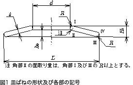
Meaning of Symbols
The symbols and units used for spring design are shown in Table 1. The values of the longitudinal elastic modulus (E) are shown in Table 2.
Table 1. Symbols and units used in calculations
| Symbol | Meaning of Symbol | Unit |
|---|---|---|
| D | Outer diameter | mm |
| d | Inner diameter | mm |
| t | Thickness | mm |
| H0 | Free height | mm |
| h0 | Total deflection(H0-t) | mm |
| E | Longitudinal elastic modulus of material (E=2.06×10⁵) |
N/mm2 |
| v | Poisson’s ratio of material(0.3) | — |
| P | Load applied | N |
| δ | Deflection of a single disc spring | mm |
| σI | Stress at position I | N/mm2 |
| σII | Stress at position II | N/mm2 |
| σIII | Stress at position III | N/mm2 |
| σIV | Stress at Position IV | N/mm2 |
| PG | Load of the spring stack | N |
| δG | Deflection of the spring stack | mm |
| n | Number of disc springs stacked in parallel | Piece |
| m | Number of sets stacked in series | Set |
| L0 | Free height of the spring stack | mm |
| R | Chamfered part’s radius | mm |
Table 2. Longitudinal elastic modulus:E(N/m㎡)
| Material | E Value | |
|---|---|---|
| Spring steel material | 206×103 | |
| Stainless steel | SUS302
SUS304(Correspond to X5CrNi18-9,1.4301,S30400) SUS631(Correspond to X7CrNiAl17-7,1.4568,S17700) |
186×103 186×103 196×103 |
Note that the chamfered amount of corner II is equal to or more than R of corner I and III.
Coefficients Used for Calculation
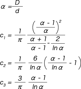
Calculation of Load
For the load (P), add the expression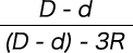 that takes into consideration the chamfer of corner R, and calculate as per the following formula.

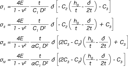
Calculation of Stress
Calculate the stress at each corner of positions I, II, III, and IV shown in Figure 2. When the value is positive, it is tensile stress. When the value is negative, it is compressive stress.
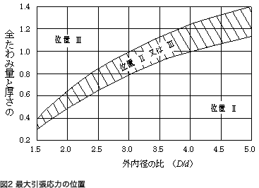
Corner Position of Maximum Stress
When examining the fatigue life, we need to examine the repeatability at the position where the maximum stress occurs from among the stress that occurs at the corners. The maximum stress position of the disc spring differs depending on the ratio of the outer and inner diameters and the ratio of the total amount of deflection to the thickness. The position where the maximum tensile stress is generated from these relationships is shown in Figure 2, therefore we can examine the maximum stress using this figure as reference.
Stacking Disc Springs
Disc springs can obtain various load characteristics depending on how they are stacked.
Method of Stacking: In Parallel and In Series
In Parallel
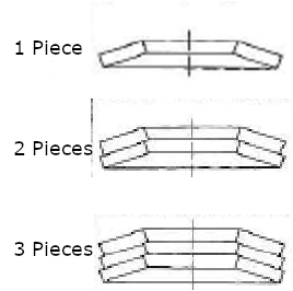
Figure 3. Parallel Stacking
・Load: Increases
・ Deflection: No change
Load: Load per single spring × No. of springs in parallel
Springs stacked in the same direction as shown in the figure.
In Series
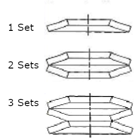
Figure 3. Serial Stacking
・Load: No change
・Deflection: Increases
Deflection:Deflection amount per disc spring × No. of springs in series
Springs stacked alternately as shown in the figure.
Change in Load and Deflection due to Parallel / Series Stacking
As shown in the figures, the load and deflection change depending on whether the springs are stacked in parallel or series.
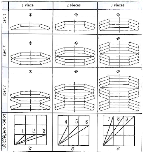
Figure 5. Changes in Load and Deflection Due to Parallel / Series Stacking
Difference between Calculated Values and Measured Values
The measured load curve is lower than the calculated load curve due to the effect of initial strain and so forth up to 40% of the total deflection, and the load increases rapidly when it exceeds 75% of the total deflection. It is recommended to try one’s best to use the spring within the range where the load characteristics are stable. The DIN standard specifies the maximum deflection for use as δ = 0.75 h (total deflection amount is δ = 0.75 h).
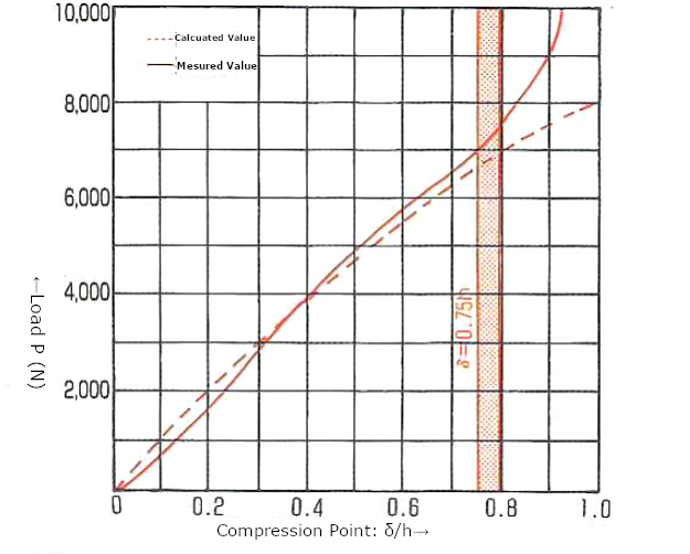
Figure 6. Difference between Calculated and Measured Values
Guides and Clearance
When using disc springs in combination, a guide (shaft, case, etc.) is required on the inner or outer diameter side. The shape of the spring changes due to compression, and so it is important to consider clearance with a guide.
Example: Change in diameter during compression
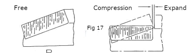
Figure 7. Change in Diameter When Disc Spring is Compressed
The inner diameter increases and the outer diameter decreases as the spring is compressed.
The table below shows the general clearance for disc springs. (As it is an in-house standard, it differs from the JIS B 2706 standard.)
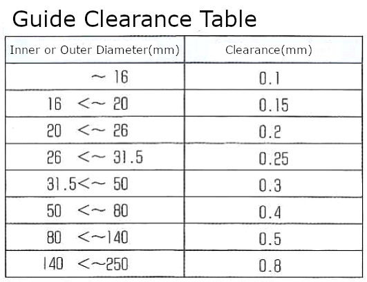
Table 3. Disc Spring Guides and Clearances
※The clearances in the table are the values for one side of the diameter. The clearances for both ends (twice the notation) are required in actual design.
 Product information
 Search By Industries
- Aerospace
- Machine tools
- Oil / Gas / Energy
- Architecture / Seismic isolation
- Engineering Science / Academic Research
- Telecommunication / Electronic equipment
- Environmental Chemical Industries
- Steel Mill Equipment
- Machinery / equipment
- Robots
- Transport equipment
- Food machinery
- Sluices / Bridges
- Special springs
- Spring Testing, Inspection, and Analysis Services
- RE:SPRING Service